How to connect a double switch. How to connect a double switch to two light bulbs. Possible errors and ways to solve them
Before purchasing and installing a two-key switch, you first need to decide what it is for? And it is designed to control two lighting circuits from one point.
Don't confuse it with pass-through switches, which have different roles. They differ in the number of contacts. Therefore, when choosing, look first of all not at the front panel, but at the back of the switch.

two-key pass-through light switch

two-gang simple switch
Let’s say if you have 2 or more light bulbs in a chandelier, using a two-key switch you can make it so that when you press one key, only half of the lamps turn on, and when you press the second, all the rest turn on at once. 
It can also control two different lamps located at separate points from each other - for example, sconces at different ends of the room or in another room altogether. 
The two-key switch differs from its single-key counterpart not only in the number of switches, but also, most importantly, in the number of contacts. There are only 3 of them here. One common and two outgoing. Through them, the phase is separated and then returned to the junction box via separate wires or directly goes to the lamps.

Please note that to install a double switch you will need at least a three-wire wire, even if you do not have a PE protective grounding conductor in your apartment wiring. 
Installation of a two-button light switch and connecting wires
There is nothing complicated in the connection diagram and in the process of installation, installation and connection of wires to the switch contacts. First of all, the switch needs to be disassembled. To do this, remove the keys themselves. If you can’t do this manually by simply pulling them towards you, use an ordinary screwdriver, prying the keys off from the side. 
As a result, what you have in your hands is the body itself with the fastenings on the sides and the internal contact part. The main task is to supply voltage from the phase conductor to the common contact. Further, when two keys are closed, this phase will diverge into one or the other lighting circuit. 
To find the central contact, look at the marking, since it may not always be located alone and in the center. 
What to do if you don’t understand the inscriptions or they are erased and painted over? Then you need to use a contact screwdriver with a battery-powered tester with a continuity test function.
Insert any metal object (nail, screw) into the supposed common contact. You wrap your fingers around it and touch the other two contacts with a screwdriver.
When you press the keys one by one, that is, turn on one - check, then turn off the first and turn on the second - check, the screwdriver LED should light up each time. If this does not happen, then this is not a common contact. 
To connect the common contact, use the conductor phase coming from the junction box gray. Strip the end of the core, insert it between the contact plates and tighten the screw with a screwdriver. 
Next, connect the other two wires in the cable to the outgoing contact connectors. 
Connecting the conductors directly to the two-key switch itself is now complete. Insert the housing into the mounting box and tighten the mounting screws. 
Then you tighten two spacer screws, which help the mounting fork with teeth to rest as much as possible against the walls of the box and firmly hold the switch body inside it. 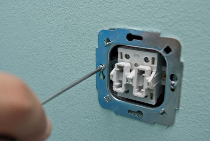 After this, you can return all the decorative frames and the keys themselves to their place.
Installation of connections for a two-gang switch in a distribution box
The following cables can enter the junction or distribution box:
- power cable from the machine in the panel
- cable going down to the switch
- one (if you have a chandelier with two lighting circuits) or two cables (if the light points are in different places) to the outgoing lamps

To avoid confusion, follow the following order:
First of all, connect all neutral conductors. They usually of blue color. Zero does not pass through the two-key switch and goes directly from the panel to the lamp, through the connections in the distribution box.
All stripped wires can be connected using Wago quick-release terminals.  Although everyone has a different attitude towards them, they are an ideal option for lighting circuits with minimal loads.
Further on everything goes well protective grounding. This is a yellow-green wire. If you do not have a grounding conductor in your apartment or the lamp body is insulated and the cable is two-core, then this connection will not be in the junction box. 
It remains to connect the phase conductors. Here you need to be extremely careful. First, clamp the phase that comes from the power supply into the Vago terminal block. Then insert a wire into the same terminal that comes from the common phase contact of the two-key switch.
You should have 4 free, unconnected wires left. Two of them are the wiring that goes to the chandelier or sconce, and the other two wires are phases connected to the lower outgoing contacts of the two-key switch.  Take two more clamps and SEPARATELY connect these conductors through them. Thus, you will connect two lighting circuits to the lamps independently of each other.
Connection to a chandelier or lamp
In a lamp or chandelier, terminal blocks are usually used for connection. Place the wires of the cable coming from the junction box onto them according to the color marking. 
A factory-made lamp must have cores of exactly the color specified in the rules. Phase - a gray or dark-colored conductor should go to the central contact of the lamp, and zero - blue to the light bulb base itself.
The yellow-green ground connection can be attached either to the terminal or directly under the screw on the housing. 
Errors when connecting a two-key switch
The first mistake that an illiterate specialist can make is to connect not a phase to the switch, but a zero.
Remember: the switch must always break the phase conductor, and in no case the zero conductor.
In the opposite situation, the phase will constantly be on duty on the base of the chandelier. And simply replacing a light bulb can end very tragically. 
By the way, there is another nuance due to which even experienced electricians can break their heads. For example, you wanted to check directly at the contacts of a chandelier whether the phase arrives there through a switch or zero. You turn off the two-key switch, touch the contact on the chandelier with a Chinese sensitive indicator - and it lights up! Although you assembled the circuit correctly.
What can be wrong? And the reason lies in the backlight, which is increasingly included with switches. 
A small current, even when turned off, still flows through the LED, applying potential to the lamp contacts. 
By the way, this is one of the reasons for blinking LED lamps in the off state. How to deal with this can be found in the article "". To avoid such a mistake, you need to use not a Chinese indicator, but a multimeter in voltage measurement mode.
The second error is when the phase supply conductor is connected not to the common contact of the switch, but to one of the outgoing ones. In this case, the circuit will not work as expected. All lights will light only if you press two keys at the same time. But if you press only the key to which the phase does not come initially, the chandelier will not light up at all. 
If you have entered new apartment, where you were not the one who connected the chandelier, and it behaves in such a strange way, that is, it does not respond as expected to the two-key switches, then the issue is most likely precisely this erroneous installation of the supply wires. Feel free to disassemble the switch and check the common contact.

If you have an illuminated switch, an indirect sign of such an incorrect connection may be the neon bulb not working properly. Why indirect? Since here everything depends on which key you start the phase on.
The third common mistake is connecting the neutral wire on the chandelier not to the common zero in the junction box, but to one of the phase wires.  To avoid this, use and follow the color coding of the wires, and even better, if you don’t trust the colors, check the voltage supply using a high-quality indicator or multimeter before turning on the lamp.
A double or two-key switch is used to control several light sources from one point. This allows you to increase or decrease the level of illumination in the room, creating greater comfort for its inhabitants. You can connect a light switch with two keys yourself, without the help of specialists. The installation of this device provides several lighting modes; the convenience of its use in everyday life can hardly be overestimated.
The design of such a switch allows one input phase to be divided into two output phases, which allows voltage to be supplied separately to two consumption sources. The device consists of:
- Two power keys.
- Decorative overlay.
- A mechanical part equipped with contact clamps for fastening power wires.

The design of some device models may include decorative key lighting based on LEDs. This helps to find the switch in the dark, and also allows you to understand that the electrical network is working and is energized.
The operating principle is simple: in the mechanical part of the switch, one incoming phase is divided into two parallel electrical circuits with separate on/off switching and device keys.
This allows you to separately supply voltage to two lighting sources or to two groups of lighting devices.
The wires in the device are fixed using screw or clamp terminals. The incoming contact clamp is located separately and is designated L. On the opposite side there are two contact clamps designated L 1 and L 2, which are used to connect two circuits of lighting devices.
Important Note
 When choosing a two-key switch to control light groups, you need to pay attention to the number of contacts in the mechanical part of the device, so as not to confuse it with a pass-through switch, designed to solve completely different problems. The pass-through switch looks like this:
It is designed to control light groups from various points in the room. For example, to turn on the light when entering a room, and turn it off near the sofa or armchair. It differs in the presence of additional fastening for a group of contacts.
Methods of application
Using a two-key switch allows you to achieve variability in the degree of illumination of the room:

The sequence of switching on and the power of lamps or light groups depends on the design of the room and the wishes of its inhabitants.
It is not always necessary to have the maximum possible number of lighting points. They can be easily turned off to save energy. Such switches are useful from a safety point of view. Controlling the lighting intensity allows you to avoid unnecessarily loading the electrical network, reducing the number of points of electricity consumption.
Connection diagrams
 There are several options for connecting a switch with two keys. Which one to use depends on the characteristics of the particular room and lighting design.
First of all, it is necessary to develop and draw a diagram of the desired connection in order to ensure that the necessary wiring is correctly laid or connected. The connection diagram also depends on the presence of network grounding. In most old apartments and private households there is no grounding wire, which is insignificant, but does affect the connection diagram of the switch. In addition, it is necessary to take into account the location of the lighting points, the number of lamps in one chandelier, as well as the location of the light points in different devices (for example, two sconces are located at a considerable distance from each other). Let's look at the most common schemes.
For two light bulbs
The connection diagram for a double switch for two light bulbs can be implemented:
- Using a ground wire.
- Without the use of a ground wire for two light sources located in one device. For example, in a chandelier.
For multi-lamp chandeliers
This scheme allows you to realize variability in the degree of illumination of the room by using a switch with two keys and a five-lamp chandelier.
- The L 1 phase activation key supplies voltage to two light points.
- When the phase L 2 key is turned on separately, voltage is supplied to three light points.
- When the L 1 and L 2 phase interrupt keys are turned on simultaneously, voltage is supplied to five light sources, providing maximum lighting power.
The number of lamps connected to each phase can be increased or decreased depending on the design of the chandelier.
The diagram shows the connection of a three-lamp chandelier using a ground wire, which is relevant for modern wiring.
Connecting two groups of lamps
This circuit allows you to connect two independent groups of light sources located at a considerable distance from each other. For example, two sconces on different sides of the room or two groups of spotlights on the ceiling. All the described connection diagrams are simple, but require care when connecting conductors.
Installation of a two-key switch
 If, when installing switches, after installing the wiring yourself, you act in accordance with the previously developed diagram, then it is almost impossible to get confused in the connection. It is much more difficult to figure out how to connect a switch with two keys to already laid wires hidden by plaster, but if you have basic knowledge of electrics, this can be done. However, safety is extremely important in any electrical work.
Security measures
220 volt voltage is always dangerous. For any electrical installation manipulations, the wiring must be de-energized by turning off the circuit breaker in the electrical panel located at the entrance to the apartment or other electrified premises. The following simple rules should be followed:
- Do not operate devices connected to the network with wet hands.
- Do not use metal fasteners for wiring.
- If the wire is visually defective, it must be replaced without resorting to repairs.
- Tools for working with electricity must have insulated handles.
Necessary tool
To replace a previously installed switch or install a new one in conditions of external wiring, as well as to install the device in a new location in a room with hidden wiring will be needed several different sets of tools. Namely:

Types of electrical wiring
 Laying electrical cables is a topic for a separate article.
External wiring is placed in a special corrugated hose made of non-flammable material and secured with clamps, clamps or clips over walls and ceilings.
Hidden wiring is placed in grooves (cuts) made in concrete or brick using a special tool - a wall chaser or using a grinder and a hammer drill, followed by cementing or plastering the channels with the electrical cable.
Wire Identification Standards
At correct installation Wiring You can identify wires by color. When installing it yourself, following the color coding will help you avoid getting confused when connecting working electrical circuits. This will reduce the time when installing certain devices and devices. The main markings look like this:
- Blue always means zero.
- Yellow wire with a green stripe - protection, grounding (used in modern electrical networks).
- A brown or red conductor indicates a phase.
There are also letter markers:
- A, B, C - phase designations.
- N is always zero.
- PE - protection, grounding.
These designations are not always visible and understandable to the average person, the standards of which have changed repeatedly over time, therefore, when installing devices in already installed wiring, you should not trust the possible accuracy of the markings. You must independently check and mark all used conductors with colored heat-shrink tubing or colored electrical tape.
Self-identification
 To do this, you will need an indicator (phase) screwdriver and a multimeter. If a single-phase network without a ground wire is laid in the room, then an indicator screwdriver will help you find the phase.
In the lighting distribution box, when the network is turned off, strip the wires and move them apart to avoid contact. After turning on the power supply, touch the wires with the tip of an indicator screwdriver. When you touch a wire with a phase present, the indicator will light up. The indicator will not react to the neutral wire.
You will need a multimeter to determine the ground wire. The device is set to the measurement limit alternating current over 220 volts. When voltage is applied, one probe touches the phase, the other touches the other two wires in series. When you touch the zero contact, the multimeter will show 220 volts; when you touch the ground, the readings will be lower.
After this, it is necessary to de-energize the network and mark the voltage supply contact group.
Connection step by step
To connect a two-key switch, you will need a three-wire wire laid from the lighting distribution box to the location where the switch is installed. If one is laid, then the task is greatly simplified. The distribution box must also contain the wires of two groups of light sources L 1, L 2 and marked conductors for supplying voltage from the electrical panel L.
 At the installation site of the switch, a hole is drilled using a crown of the appropriate size and a socket box must be installed. If there is an already drilled hole with a socket box, then it is advisable to replace the socket box before installing a new device. If external wiring is installed in the room, then the switch is installed in a specialized container, which is fixed to the wall with screws.
In the mechanical part of the switch, a common input terminal is determined - the mount and wire L is connected to it (voltage supply from the electrical panel), having previously marked it in the distribution box accordingly. The other two phase wires are connected to separate terminals, designated L 1 and L 2.
After connecting the conductors, the mechanical part of the switch is fixed in a socket box or container so that in the off position the keys are recessed down (this corresponds to the accepted standard), avoiding distortions and displacements.
Assemble the decorative part of the device, install the frame and keys.
In the distribution box, conductors are connected in accordance with the markings using Wago connections or contact strips.
- Phase L coming from the electrical panel is connected with wire L going to the input of the switch.
- Parallel phases L 1 and L 2 coming from the switch output are connected to the phase inputs of the light groups L 1 and L 2.
- Zero outputs are switched into one connection.
- Protection and grounding wires are also connected into one whole, if any.

Twisting the wires is strictly not recommended. This method of switching conductors is not reliable. The weakest points in electrical wiring are the connections. Insecure connections can lead to loss of contact or overheating and fire.
It must be remembered that a phase wire is always routed to the switch. Otherwise, the assembled electrical circuit will not meet safety standards.
Installing a two-button switch is a simple task that can be easily handled by a person who has a superficial understanding of electricity. But when starting work, you need to pay special attention to safety precautions and always remember that a voltage of 220 volts is dangerous.
WITH connection diagram for two-key switch can cause difficulties for many unprepared people. However, in reality everything is very easy and simple. You can verify this by reading the detailed installation and connection instructions presented in this article. By adhering to it, you can easily not only understand the circuit, but also perform independent installation with your own hands. presented in the form step by step photo instructions with detailed comments and explanations, which makes it as accessible and understandable as possible even for ordinary untrained people.
A double switch is quite convenient in a lighting control system, as it allows you to control the light in two directions from one place. The most common example of such use is a two-gang switch installed to turn on the light in a separate bathroom and toilet. Also, two-key light switches are used to control individual groups of lighting lamps in multi-arm chandeliers, but in Lately this fashion began to become a thing of the past, as the lighting equipment market has changed quite a lot; in modern chandeliers the double switch has replaced remote management.
In our example, we will consider the connection diagram of a two-key switch and its sequential installation for two rooms. In the most compact form, it will be presented that which is usually located under the plaster at a distance from each other. We’ll also look at a clear example of how to connect a two-key light switch.
Installation of pre-installation circuit elements
Let's start by installing the junction box. In the subsequent stages of installation in it, we will collect all the wires necessary to complete the circuit, and then connect their cores in a certain sequence.

We also need a protective device that will protect the lighting circuit from short circuit currents and overloads. Usually, it is installed in the power panel, but in our case, for greater clarity, we will install it on the rail next to the circuit.

Now, installing a socket box, we will install a two-key switch in it.
You can see how to carry out the actual installation on our website in the relevant instructions, and.

The main elements are prepared, let's move on to installing the wire.
Laying the wires necessary to implement the two-key switch circuit
First, we mount the power wire; it will be connected to the protection device. In our example, we use a 3*1.5 brand wire - three-core, with a core cross-section of 1.5 square. A three-core wire is universal, since the third core can be used if necessary, for example, to ground a lamp.
Attention! If there is voltage on your suitable wire, before carrying out all work you must turn it off, and then additionally make sure that there is no voltage on the wires using .

Now, we lay the wire that will power the distribution box, from the protection device to the box.


The ends of the wires coming to the junction box must be left with a margin of 10-15 centimeters.  A supply of wire is also needed on the socket box; 10 centimeters will be enough.

Next, we mount the wire to the lamp of the first room.


All the necessary wires to complete the connection diagram for a two-key switch are installed.

Connecting protection, control and lighting devices
Let's start by installing the lighting circuit protection device. For our example, a two-pole circuit breaker is used; the rating should be calculated for each individual case individually, since the lighting power will be different everywhere. In some places there will be only one 150 W lamp, and in other cases there will be several 3 kW spotlights.
The wire we use has double insulation, common outer and inner, separate for each core.
Carefully, without damaging the internal insulation of the cores, remove the outer layer. First, from the wire supplying the protection device.

Then, from the wire going to the junction box.

We measure the length of wire required for connection. We bite off the excess. Then, remove the insulation from the wires and connect the wires to the terminals. The wire has a different color for each core.
- We define the blue core to transmit zero;
- Yellow with a green stripe - for grounding;
- We use the remaining core for phase transmission. In our case, the phase on the wire approaching the machine is white with a black stripe, and on the wire going to the junction box it is simply white.
When making connections, carefully ensure that the upper wires suitable for the machine match the colors of the lower ones. At the top, the phase is on the left, at the bottom there should be the same on the left. At the top, zero is on the right, so the bottom should be on the right.

We will not use grounding conductors in our example, but in principle, they can be used to transfer grounding to the corresponding contacts of the lamps. Unless, of course, it is structurally provided for in the electrical supply system of your home.
Many lamps have a metal body and are designed with a grounding contact. This is especially true in rooms with high humidity.
We isolate the unused grounding conductors and put them aside so that they do not interfere. 
Let's move on to connecting the two-key switch.

We strip the wires and remove the outer insulation.


Now, let's look at how to connect a double light switch.
Our example uses a switch with plug-in contacts.

We turn the mechanism with the back side. As you can see, it shows a wiring diagram for a specific switch. As a rule, such a scheme is found on all lighting control devices, but there are exceptions. Connecting two-button switches of various types is described in great detail in the instructions.
Following the symbols of the switch circuit, we connect the wires. In our case, “L” is the suitable phase, and the two arrows at the bottom of the phase are outgoing.

Let me remind you that in our example we chose a core for phase transmission white. There is a corresponding contact for it on the switch, for a specific model it is designated by the letter “L”, a contact of a suitable supply phase.

We connect the two remaining strands of the wire to the outgoing contacts, on this model they are indicated by arrows, from them the phase, at the command of the keys, will be supplied to the lamp of the first or second room, or to both rooms at once.

The switch is connected. We install it in the socket box.

You can see more details on how to install other electrical wiring elements (sockets with and without grounding, double switches, including backlit ones, chandeliers, lamps, bathroom exhaust fans).
Let's continue. The lighting control element is installed, all that remains is to mount the lamps. In our example, they are presented in the form of two sockets with light bulbs.

We prepare the wires of the first and second lamps for connection. We remove the outer insulation, measure out the required amount of wire, and strip the core for connection. As a rule, lamps are equipped with standard plastic terminals; to connect through them you will need approximately 0.5 centimeters of bare wire strand

We connect the lamp of the first room, also known as a socket.

Then, the lamp of the second room.

Ground wires are not used in our example, so we isolate them.

And we put it aside so that it doesn’t get in the way.

All circuit elements are installed. Now, let's move on to the actual assembly of the circuit. 
Connecting wire cores into a two-key switch circuit
We begin assembling the circuit with the supply wire.

We remove the outer insulation from it.

Then, we prepare the next end of the wire, going from the junction box to the two-key switch.

Using a knife, we strip 4 centimeters of insulation from each core of both wires.

Next, according to the diagram, the phase should arrive at the switch. Therefore, we connect the two white wires of the supply wire and the wire going to the switch to each other. And then we twist them clockwise, first by hand, then pull them through with pliers. According to the textbook, the twist should be 5-7 turns, bite off the excess.
At this stage I would like to draw your attention to one important point. The example uses the twisting method, as it is the most visual for understanding and perceiving the principle of the circuit. Currently, the rules for the design of electrical installations in their pure form are prohibited by PUE clause 2.1.21.
Permitted methods for connecting wire cores include:
- crimping;
- welding;
- soldering;
- screw, clamp and similar clamps.
This issue will be discussed in more detail in the corresponding instructions; the article is currently being written, but will appear on our resource in the near future.
Let's continue. The first connection of the wire cores has been completed.

The grounding conductor of the supply wire is not particularly useful in our example, so we insulate it with insulating tape. 
Now, we prepare the wire going to the lamp of the first room. We remove the insulation of the wire and strip the wires.


We connect the phase white wire of the lamp of the first room with one of the outgoing wires of the two-key switch, take the blue wire.

We also do not use the grounding core of the wire going to the lamp of the first room, so we insulate it.

We prepare the wire for the lamp in the second room, remove the insulation, and strip the wires.

We isolate the grounding conductor.

We connect the white phase wire of the lamp in the second room with the outgoing yellow-green wire of the switch.

We remove all unnecessary insulated grounding conductors into the distribution box.

We still have three neutral wires left unconnected, two from two lamps and one from the wire feeding the junction box. Let's connect them together.

The connection diagram for the two-key switch is ready. We screw the light bulbs into the lamps.

And we move on to testing the circuit.

Apply voltage. We turn on the circuit breaker, for which we move the control lever to the upper position.


Voltage is applied. Now, let's test control the lighting of the rooms. We move the first key of the switch to the “on” position, voltage is supplied to the first lamp, as a result of which the light in the first room lights up.

We turn the first switch key to the “off” position, the light in the first room goes out. Now, we check the operation of the second switch key, to do this we move it to the “on” position, voltage is supplied to the lamp of the second room, the light comes on.
 We turn the second switch key to the “off” position and the light in the second room goes out. Let's do one last test. We move the first and third keys simultaneously to the “on” position, the lights come on in two rooms.

We move both keys to the “off” position, the lights went out in the first and second rooms. Testing is completed, the circuit is working correctly.
Turn off the voltage by moving the circuit breaker lever to the down position.
Use insulating tape to insulate the twists.

We put the frame on the switch.

The circuit is ready for operation.
Drawing. Double switch connection diagram.

To complete the double switch connection diagram we used:
Material
- machine mounting rail (Din rail) - 1 pc.;
- two-pole circuit breaker - 1 pc.;
- distribution box - 1 pc.;
- lamps (for our example, sockets with lamps) - 2 pcs.;
- socket box - 1 pc.;
- two-key switch - 1 pc.;
- wire VVGngP - the amount of wire required depends on the size of each specific room;
- insulating tape - 1 pc.;
- fastening perforated tape - the required quantity depends on the meter of the wire;
- dowel-nails.
Tool
- Phillips screwdriver (screwdriver);
- flat screwdriver (screwdriver);
- voltage indicator;
- pliers;
- wire cutters;
By completing the connection diagram for a two-key switch with our own hands, we saved:
- - 200 rubles;
- installation and connection of a two-pole circuit breaker - 300 rubles;
- installation and connection of an indoor distribution box - 550 rubles;
- installation and connection of ceiling lamps (450 rubles for 1 lamp) - 900 rubles;
- installation of an indoor socket box (brick wall) - 200 rubles;
- installation of a two-key hidden switch - 150 rubles;
- laying the wire openly no higher than 2 meters (1 meter - 35 rubles), for example, let's take 2 meters - 70 rubles;
- laying the wire openly above 2 meters (1 meter - 50 rubles), for example, let's take 8 meters - 400 rubles;
- wall chipping 8 meters (1 meter - 120 rubles) - 960 rubles.
Total 3730 rubles
*Calculation provided for hidden wiring
Modern life is difficult to imagine without electricity. The availability of electricity is an important factor for all areas of human activity. Electrical appliances surround us everywhere, making life more comfortable and favorable.
Features of installation work in the electrical field
Planning
Electrical wiring helps keep your entire home lit and functioning. household appliances. Electrical installation is not an easy task, requiring special knowledge, skills and abilities. Even a beginner can figure this out if they use the right information.
You need to start working with planning. You should carefully inspect the entire house, decide on the type of lighting, the optimal placement of sockets and switches in each room. Next, you should draw up a network diagram, indicating the specific location and dimensions of each element.
The entire network chain (network chain) is divided into several groups:
- lighting network;
- socket;
- automatic power supply units for individual appliances (air conditioners, boilers, heating boilers, refrigerators).
The humidity level of the room is taken into account. The current-carrying conductor in the basement, bathtub, and toilet passes exclusively through a differential circuit breaker. Having determined the power strips, you should calculate the voltage level. Depending on this, a cable of the required cross-section and thickness is selected.
Important aspects of wiring operation:
- determining the best wire cross-section;
- panel connection;
- protective shutdown device.
The choice of the type of current-carrying cable is influenced by the following factors:
- material of manufacture;
- wire length;
- operating temperature;
- air humidity;
- cable brand;
- number of phases;
- connection method.
The wire cross-section directly depends on the voltage level. The higher it is, the more powerful the cable. For example, a voltage of 2 kW is normally supported by a copper cable with a cross-section of 2 mm.

Copper cable with a cross section of 2 mm
In the middle of flammable structures, the cable is laid in a corrugation. One side fits into the mounting box, the other goes into the shield. Be sure to leave 40-50 centimeters in reserve. The shield is connected after the cable has been pulled.
In rooms with high humidity levels, a differential circuit breaker or residual current device is installed. The devices provide safety against electric shock due to poor insulation. Nowadays, it has become popular to lay wiring under the floor (it allows you to save on consumables).
Structural device of double switch
The main attributes for home lighting are a lamp and a switch. The switch-off device ensures that light appears at the right time for a person. The main task is to correctly connect/disconnect the current going to the light bulb.
Switches have different quantities keys:
- one;
- and more.
An excellent solution to the problem of lighting control are two-key switches.

Double switch device
When working with lighting, the question often arises: First you need to choose the right device that matches the color, design, and size. Universal colors: white, beige, ivory. They fit any design.
Installation and installation of switches begins with familiarization with the design elements.
Device structure:
- frame;
- two keys;
- input/output terminals/clamps.
The application diagram is attached to the product. The schematic structure is that two keys control two lights. The electrical phase is supplied through a switch. Pressing the key disconnects the pass-through path of the phase wire circuit. The circuit of three working contacts is located on the back of the panel.
Outgoing contacts are always located opposite to the incoming one. One common one goes to the phase, two opposite ones go to the control outputs.
The two-key device is installed using terminals or screw clamps. The switch wires with clamps are located in a specific block; they are secured with U-shaped screws and washers.
The main disadvantage of screw fastening is that after frequent use, the clamps may unscrew without permission and the mechanism will begin to function poorly. The defect is eliminated by unscrewing the case and tightening the screws. Self-closing terminals prevent such problems from occurring.
Connection sequence
The lamp begins to glow when zero and phase are applied.

Double switch connection diagram
Modern wiring is done with a three-core cable with multi-colored wires. These wires fit to the mounting location of the lamp. Before connecting, you need to determine the purpose of the wires. A conventional two-gang switch has three contacts.
The sequence of light in the room has its own specifics:
- First you need to de-energize your home by turning off the switch on the disconnect panel or circuit breakers
- You can check that the current is turned off by inserting the lamp into the socket (if it doesn’t light up, then everything is turned off);
- before installation, exposed parts must be cleaned;
- the pass-through neutral wire from the switchboard must be combined with two contact groups;
- the second phase wire from the shield is attached to the wire going to the common contact;
- the color of the wires of different groups should be different (the first wire is connected to the phase of one group of lamps, the second is connected to another group);
- phase wires are attached to their consumer groups;
- the neutral wiring from the panel is connected to the neutral wiring of the lamps (a two-key switch combines two groups of consumers);
- safety needs to be carefully considered large quantity associations located in the cutting box (twist well, solder);
- the switch is carefully attached to the box on the wall (the mounting wire is very stiff);
- a decorative frame is attached to the base, the button block is inserted into the grooves and securely fixed to the body;
The voltage indicator will help you check whether the pass-through switch is functioning correctly. Sometimes it becomes necessary to install a two-button switch complete with a socket. In this case, an additional section of wire is laid from the switch to the socket. The height of the device is very varied: the main thing is to be comfortable.
How to find a phase wire?
To properly connect a double switch, you need to decide on the wires. Sometimes doubts arise which wire is phase.
The following method will help to clarify the situation:
- the ends of the wires are carefully moved to the sides (so as not to butt together);
- the voltage on the panel turns on;
- use an indicator screwdriver to touch the exposed parts;
- The phase wire is the wire that, when touched, will light up the light bulb.
Dimmers help control lighting intensity. There are touch, push, rotary. The installation diagram is the same for all types.
Two-key devices are more compact and elegant than several single-key devices installed together. Carefully following the instructions will help you install the pass-through switch correctly (at the proper level) to suit your needs.
Precautionary measures
What measures should be taken when installing light in the house? Working with a voltage circuit requires a careful approach, taking into account safety rules.
To avoid injuries/accidents, before connecting the two-gang switch, you should properly turn off the current supply and check for voltage on the input cable.
Safety regulations:
- It is better to begin work on installing sockets/switches before design renovation.
- Before starting installation, check the condition of the electrical wiring.
- Properly organize actions during daylight hours (it is more difficult to install in the dark).
- Be sure to check the serviceability of light bulbs and other parts.
- Use a voltage indicator to check that the current supply is disconnected.

Voltage indicator to check current interruption
- Turn off the circuit breakers or package switches on the home panel.
- In accordance with safety standards, it is correct to use red phase wiring. The neutral wire is blue.
- Carry out all actions with extreme caution.
To avoid electric shock, special attention is paid to areas with high humidity levels. The power supply to the porch, bathtub, and basement requires the use of reinforced insulation. The light bulb is replaced when the electricity is turned off.
Using a ladder, place an insulation mat at the base. After connecting the electrics, there should be no dangerous areas in the house. Contacts are connected in compliance with all technical standards.
Additional Information
How to properly prepare wiring for normal operation of equipment? New wires in the box require preparation for connection. Best job provide exiting ends approximately 100 mm long. Long parts are shortened with forceps. Extended short conductors can create a short circuit.
The joints of the ends are pressed well with pliers and wrapped with insulating tape/adhesive tape. Excellent insulation protects against short circuits. Before placing the wires in the terminal sockets, about 15 mm of insulation is removed from the ends.
The minimum set of installation tools consists of the following items:
- cross-head screwdriver;
- pliers;
- voltage indicator;
- portable flashlight
- electrical knife;
- additional electrical wiring 1.5 meters long.

Set of tools for electrician work
Connection. Video
This video will tell you about connecting a two-key switch from “A” to “Z”. The right approach will ensure uninterrupted power supply in the future.
Living comfort consists of many components, among which lighting system control plays an important role. It can be made more convenient by installing two-key electrical appliances.
Agree, it would be nice to learn how to do such work yourself, especially if you have to major renovation housing and updating electrical wiring. But before you connect a double switch to two light bulbs, you need to decide on the circuit and study the procedure.
We will help you achieve your plans. The article describes the nuances of implementing different connection schemes, and also provides step-by-step instructions for installing a two-key switch. The text material is supplemented with visual illustrations and video reviews.
An experienced electrician begins any project to improve a lighting system by optimizing the use of all electrical devices combined into one chain.
An example of an optimized circuit is the traditional lighting arrangement of the “toilet + bathroom” block. On the corridor side, one switch is usually installed, but with two keys.
Thus, the lamp in the bathroom is controlled by one key, and the light bulb in the toilet is controlled by a second. With one movement of your hand, you can perform two actions at once, turning off the lights in one room and turning on the lights in the next one, which is very convenient.
If the switch is installed in the wall between two parts of the bathroom, then choosing a key will not be difficult - it will be located on the side of the desired room
Installing a common switch for two rooms is advisable if they are located nearby. For rooms remote from each other, it is reasonable to use separate electrical installations.
A double switch may also be required when installing a chandelier or sconce with two bulbs. Separate control expands the functionality of the lighting device and allows you to increase or decrease the combustion intensity.
If you press one key, the lighting will be inadequate; when you press both keys, it becomes twice as bright.

To save energy, it is not necessary to use both bulbs at the same time. To create a relaxing atmosphere, it is enough to turn on only one of them
As you can see, the ability to connect a double switch to two separate light bulbs makes it easier to control lighting fixtures or adjust light intensity. When installing a single device for two rooms, not only electricity is saved, but the number of installation materials and devices is reduced.
How to choose a circuit for two light bulbs
There are differences in the connection of 1-key and 2-key switches. To better understand the difference, let's first look at the installation nuances of a single-keyboard player.
You can connect one or more light bulbs to a regular switch with a single key - the principle remains the same.

The diagram shows an option using a two-core cable, without using ground. The neutral core is pulled directly to the lighting fixture, and the phase is connected to the switch, from where it goes to the light bulbs (+)
This is the most simple circuit, it is traditionally used when simple control of a luminaire is required or whole group. When the electrical installation is turned on, all involved light sources light up. If there is a chandelier or sconce with two lamps, then both will turn on at once; it will not be possible to use them one at a time.
Now let’s look at what changes if a single-key device is replaced with a two-key device. The first circuit for connecting a double switch to two separate light bulbs is relevant for the TN-C system, which is still found in old houses. For the lighting circuit, two-core wires are used.

The zero is sent through the junction box directly to the lamps connected in series, and the phase goes to the input terminal of the switch. But the output is already double: a phase conductor goes from each of the output terminals to a separate lamp (+)
It turns out that you can use either one or both light bulbs at the same time, using either one or two keys.
A positive point is the ability to change the lighting intensity in one room. If the lamps are in different rooms, then you can turn on the lights in each room separately or in both at once.
In new houses, grounding systems that differ in design are used, for example, TN-S. The difference between the second scheme for a home electrical network is that a three-wire wire is required: the third wire is the “ground”.

Like the neutral conductor, the grounding conductor is sent to the distribution box, and then connected to the wires of the lamps and connected to metal parts (+)
The grounding wire is connected differently if there is an outlet in the same block as the switch. Then the “ground” from the electrical panel reaches to the distribution box, and from there to the outlet.
Step-by-step installation instructions
Conventionally, connecting a switching device can be divided into several stages. They start with the cables: if the wiring is old, then it definitely requires replacement.
Then you need to correctly connect the wires in the junction box, and finally in the switch mechanism. To install a chandelier or lamp, you usually use the instructions provided by the manufacturer.
Stage #1 – preparing the walls
Soldering is used extremely rarely. If you are used to using terminal blocks, then you can consider the option of a distribution box with pre-installed terminals.
Stage #3 – installation of lamps
Whether it is done with two lamps or two separate lamps depends on many factors:
- lighting fixture models;
- wiring readiness;
- basics for installation.
The easiest way to change lighting equipment is when the wire is routed out at the installation location, for example, in the center of the room.

To install a chandelier, you need to perform two operations: hang the lighting fixture on a hook or bracket and connect the wires correctly
If the ceiling is new and is a suspended structure (tension, plastic or plasterboard), then additional fasteners or mortgages should be installed to install the chandelier.
When two phase wires are supplied from a two-key switch to the lamp, they are connected alternately - each to its own lamp. Also, two neutral wires are pulled from the distribution box - they are also scattered among different lamps.
If both bulbs are connected to the same wire, they will turn on/off at the same time, and there is no point in installing a double switch.
When installing two separate lamps in different rooms, the connection principle remains the same, only the routing of the wires from the junction box changes - they are directed to different sides. As a rule, the rooms are located next door. It is better to mount the distribution box above the switch, approximately 15-20 cm from the ceiling.
Stage #4 - installation of the switch
There are no difficulties in either installation or connecting the two-keyboard. It is installed in a socket box or directly into the wall, secured with claws or a screw connection. Exactly how the wires are connected is shown in the photo.

The double switch is always connected only to the phase conductor coming from the distribution box, where it comes from the electrical panel. The core is inserted into the terminal marked “phase L”. From the output contacts L1 and L2, the phase conductors go to the lamps (+)
If the chandelier has not two, but more lamps, which is much more common, then the connection is made in groups. All lamps are divided into two equal or unequal groups, and then the wire from contact L1 is directed to one, and the wire from contact L2 to the second.
Conditional division into groups is made depending on the desired degree of illumination of the room. If you need two intensity modes, weak and bright, then you can connect the first core to one lamp, and the second to the rest. To reach the maximum brightness level, just press both keys.
There are several important points that should not be forgotten. They relate to both installation work and equipment selection.
Performance simple rules will make the system more secure and reliable, which is important for a closed network.
Image gallery

All work on connecting electrical equipment in the distribution board is carried out by qualified electricians servicing the house. It is not recommended to independently interfere with the security system located on the site

For external wiring, special materials are used: a cable in durable insulation, ceramic rollers on which it is mounted, and a surface-mounted switch. Products from the same collection look more aesthetically pleasing

If it is not possible to rent a wall chaser, then the grooves can be cut with a circular saw, but this is a difficult and time-consuming task. To ensure that the grooves are even, it is recommended to first make precise markings on the walls

For accurate installation of switches, socket boxes are used, as for sockets. These are polymer boxes made of non-flammable material that must be secured in a wall hole. Installation is carried out on fastenings, the gaps are covered with alabaster

To ensure your own safety, during electrical installation you must use screwdrivers and insulated pliers, as well as special gloves and instruments for measuring voltage in electrical installations - testers and indicators

To twist or insert wires into terminals, the ends of the wires must be freed from the insulating braid - stripped. To do this, use a sharp stationery or construction knife, as well as special pliers - strippers.

Traditionally, color marking is used to indicate the load of the cores: phase - red, brown, black; zero – blue or blue-white; earth – green or yellow-green. However, the installed wires may be mixed up, so double-checking is necessary

Junction boxes and socket boxes have limited internal space, so it is necessary to cut off excess wires. However, you should always leave a small margin for subsequent replacement of electrical equipment or reconnection