Accurate voltmeter on arduino. Digital voltmeter on Arduino with connection to a PC via a serial port. Analog Input Software Features
Schematic diagram homemade bipolar voltmeter on Arduino Uno and with 1602A display. In the article “Double voltmeter on ARDUINO UNO” (L.1), the author proposed a description of the voltmeter and a program for simultaneous measurement and indication of two constant voltages. Which is very convenient if you need to simultaneously measure two constant voltages and compare them.
This may be required, for example, when repairing or setting up a DC voltage stabilizer in order to measure the voltage at its input and output, or in other cases.
However, there are circuits with bipolar power supply, when the voltage at some point in the circuit relative to the common “zero” can be either positive or negative.
Schematic diagram
Here we describe the modification of the circuit and program so that the device can measure and display both positive and negative voltage.
To begin with, the measured voltages are supplied to two analog inputs A1 and A2. There are six analog inputs in total, A0-A5, you could select any two of them. In this case, A1 and A2 are selected. The voltage on analog ports can only be positive and only in the range from zero to the microcontroller supply voltage, that is, nominally, up to 5V.
The output of the analog port is converted into digital form by the microcontroller's ADC. To get the result in units of volts, you need to multiply it by 5 (by the reference voltage, that is, by the supply voltage of the microcontroller) and divide by 1024.
Rice. 1. Schematic diagram of a bipolar voltmeter on Arduino Uno and 1602A.
In order to be able to measure voltages greater than 5V, or rather, greater than the supply voltage of the microcontroller, because the actual voltage at the output of the 5-volt stabilizer on the ARDUINO UNO board may differ from 5V, and usually a little lower, you need to use conventional resistive dividers at the input.
Here these are voltage dividers across resistors R1, R3 and R2, R4. But what if the voltage needs to be measured less than zero? In this case, there is only one way out of the situation - to raise the level of the input zero. Ideally, you need half the supply voltage, that is, up to 2.5V. In this case, 2.5V data will be added to the input voltage.
Then, programmatically, simply subtract this voltage from the measured one. But, this will require an additional source of this voltage. In principle, this is not difficult to do, but there is a simpler solution.
In addition to the 5V voltage stabilizer, the ARDUINO UNO board has a 3.3V voltage source. So it can be used as a “virtual zero” for entry.
Changes in the circuit are visible in Figure 1. Compared to the first option, the input “zero” is simply rearranged from the common zero to the +Z.ZV source. Therefore, when the input voltage is positive, at the input it is more than 3.3V (but not more than 5V - this is the upper limit of measurement), and when negative - less than 3.3V (but not less than OV - this is the lower limit of measurement).
An increase in the measurement limits (modulo) is achieved by a resistive divider, and the indication of the actual input voltage supplied to X2 and X3 is achieved by software subtraction of a value of 3.3V from the voltage at the microcontroller inputs.

The program is shown in Table 1. This can be seen in the lines:
volt=(vout*5.0/1024.0-3.3)/0.048 ;
voltl=(voutl*5.0/1024.0-3.3)/0.048;
The number 3.3 is exactly this voltage of the “virtual zero” input.
In these lines, the number 5.0 is the voltage at the output of the stabilizer of the ARDUINO UNO board. Ideally, it should be 5V, but for the voltmeter to work accurately, this voltage must first be measured. Connect the power source and measure the +5V voltage at the POWER connector of the board with a fairly accurate voltmeter.
What happens, then enter in these lines instead of 5.0. The same applies to the voltage +3.3V - it needs to be measured at the board connector, because in fact it may differ slightly from 3.3V. For example, if "5V" is actually 4.85V and "3.3V" is actually 3.32V the lines would look like this:
volt=(vout*4.85/1024.0-3.32)/0.048;
voltl=(voutl*4.85/1024.0-3.32)/0.048;
At the next stage, you will need to measure the actual resistances of resistors R1-R4 and determine the K coefficients (indicated as 0.048) for these lines using the formulas:
K1 = R3 / (R1+R3) and K2 = R4 / (R2+R4)
Let's say K1 = 0.046, and K2 = 0.051, so we write:
volt=(vout*4.85/1024.0-3.32)/0.046;
voltl=(voutl*4.85/1024.0-3.32)/0.051;
Thus, changes must be made to the program text according to the actual voltage at the output of the 5-volt and 3.3-volt stabilizers of the ARDUINO UNO board, and according to the actual division coefficients of the resistive dividers.
After this, the device will work accurately and will not require any adjustment or calibration. When measuring a negative voltage on the LCD indicator, there will be a minus sign in front of the voltage value in the corresponding line. When measuring positive voltage, there is no sign.
By changing the division coefficients of the resistive dividers (and, accordingly, the “K” coefficients), you can make other measurement limits, and not necessarily the same for both inputs.
I would like to remind you that the H1 type 1602A liquid crystal display module is connected to the digital ports D2-D7 of the ARDUINO UNO board. The LCD indicator is powered by a 5V voltage stabilizer located on the 5V voltage stabilizer board.
In order for the indicator to interact with ARDUINO UNO, you need to load a subroutine into the program to control it. Such routines are called "libraries", and there are many different "libraries" in the ARDUINO UNO software package. To work with an LCD indicator based on the HD44780, you need the LiquidCrystal library. Therefore, the program (Table 1) begins by loading this library:
This line gives the command to load this library into ARDUINO UNO. Then, you need to assign ARDUINO UNO ports that will work with the LCD indicator. I chose ports D2 through D7. You can choose others. These ports are assigned by the line:
LiquidCrystal led(2, 3, 4, 5, 6, 7);
After which, the program proceeds to the actual operation of the voltmeter.
Karavkin V. RK-06-17.
Literature: 1. Karavkin V. - Double voltmeter on ARDUINO UNO. RK-01-17.
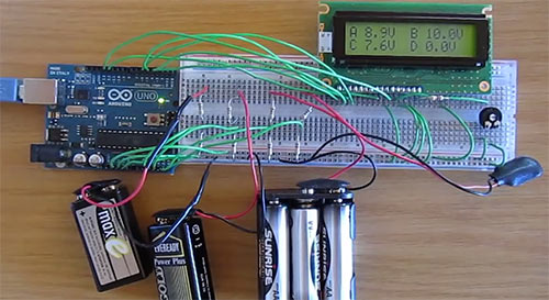
Four-channel "Arduino-"voltmeter" can measure four independent DC voltages in the range from 0 to 50V. Analog channels A2 to A5 on the Arduino Uno are used to measure four different voltages. The measured voltage values are displayed on a 16-character, two-line LCD display.
Voltages are displayed as a single decimal value, e.g. 5.3V, 12.8V, etc.
The video below shows an Arduino-based voltmeter in action that measures the voltage of four batteries at different voltage levels.
The principle of operation of a voltmeter
Each channel of the Arduino-based voltmeter has a pair of resistors that form a voltage divider. A voltage divider reduces the input voltage to a level that can be measured by the Arduino microcontroller. The Arduino code running calculates the actual voltage value and displays the result on the LCD.
Before you begin assembling the circuit, make sure that your LCD display has the same number of pins as the display shown on the schematic. If connected incorrectly, the LCD may be damaged.
In this educational material shows how to connect an LCD display to an Arduino Uno board.
Voltage is measured between points A, B, C or D and ground or 0V. Be sure to adjust the contrast level using the potentiometer so that the reading on the LCD is visible.
Resistor R1 provides current limiting for the optional backlight and allows it to be always on.
Sketch of a voltmeter based on Arduino
The variables sum and voltage are combined into an array, which allows you to store readings from four analog channels.
Calibration
The calibration process is described in detail in the article Measuring DC Voltage Using Arduino, but in our case we need to calculate the division ratio of 4 voltage dividers.
The calibration values can be easily changed at the top of the code:
// voltage divider calibration values #define DIV_1 11.1346 #define DIV_2 11.1969 #define DIV_3 11.0718 #define DIV_4 11.0718 // ADC reference voltage / calibration value #define V_REF 4.991
Reference Voltage Calibration
Measure the 5V voltage and change the V_REF constant values according to the measured value. Measure the voltage in the circuit with the LCD connected and the sketch running, as the voltage may change when the LCD is connected. For example, with a connected circuit, the voltage value from 5.015V with the LCD display disconnected can drop to 4.991V with the LCD display connected on the same hardware.
Voltage Divider Calibration
Change the voltage divider values for each voltage divider from DIV_1 to DIV_4 at the top of the sketch. DIV_1 - DIV_4 correspond to analog pins A2 - A5.
List of radioelements
| Designation | Type | Denomination | Quantity | Note | Shop | My notepad |
|---|---|---|---|---|---|---|
| Arduino board | Arduino Uno | 1 | To notepad | |||
| R1 | Resistor | 47 Ohm | 1 | To notepad | ||
| R2, R4, R6, R8 | Resistor | 1 MOhm | 4 | To notepad | ||
| R3, R5, R7, R9 | Resistor | 100 kOhm | 4 | To notepad | ||
| RV1 | Trimmer resistor | 10 kOhm | 1 | To notepad | ||
| LCD | LCD display | 16x2 HD44780 | 1 |
There are times when you want to check voltage or some point in a circuit, but you don't have a voltmeter or multimeter at hand? Run to buy? It's long and expensive. Before you do that, how about building a voltmeter yourself? In fact, with simple ingredients you can make it yourself.
Step 1: Prepare the components

- In the lesson we used a board compatible with Arduino - SunFounder Uno / Mars (http://bit.ly/2tkaMba)
- USB data cable
- 2 potentiometers (50k)
- LCD1602 - http://bit.ly/2ubNEfi
- Development board - http://bit.ly/2slvfrB
- Multiple jumpers


Before connecting, let's first understand how it works.
Use SunFounder Uno board for the main part of the voltmeter data processing, LCD1602 as the screen, a potentiometer to adjust the LCD contrast, and another to divide the voltage.
When you rotate the potentiometer connected to the Uno board, the potentiometer resistor changes, thereby changing the voltage across it. The voltage signal will be sent to the Uno board through pin A0, and the Uno will convert the received analog signal into digital form and record on the LCD. This way you can see the voltage value at the current capacitance resistance.
LCD1602 has two operating modes: 4-bit and 8-bit. When MCU IO is insufficient, you can choose 4-bit mode, which only uses pins D4~D7.

Follow the table to connect them.
Step 4: Connect the potentiometer to LCD1602

Connect the middle pin of the potentiometer to the Vo pin on the LCD1602 and any of the other pins to GND.

Connect the middle pin of the potentiometer to pin A0 from the SunFounder Uno, and one of the others to 5V while the other to GND.
Step 6: Upload the code
This code:
#include /****************************************************** *****/ const int analogIn = A0;//potentiometer attach to A0 LiquidCrystal lcd(4, 6, 10, 11, 12, 13);//lcd(RS,E,D4,D5,D6.D7) float val = 0;// define the variable as value=0 /*********************************** *****************/ void setup() ( Serial.begin(9600);//Initialize the serial lcd.begin(16, 2);//set the position of the characters on the LCD as Line 2, Column 16 lcd.print("Voltage Value:");//print "Voltage Value:" ) /****************** **********************************/ void loop() ( val = analogRead(A0);//Read the value of the potentiometer to val val = val/1024*5.0;// Convert the data to the corresponding voltage value in a math way Serial.print(val);//Print the number of val on the serial monitor Serial.print ("V"); // print the unit as V, short for voltage on the serial monitor lcd.setCursor(6,1);//Place the cursor at Line 1, Column 6. From here the characters are to be displayed lcd.print(val);//Print the number of val on the LCD lcd.print("V");//Then print the unit as V, short for voltage on the LCD delay(200); //Wait for 200ms )
Rotate the potentiometer to check the voltage on the LCD1602 in real time.

Here's a tricky thing. After I ran the code, the LCD showed characters. I then adjusted the screen contrast (gradual change from black to white) by turning the potentiometer clockwise or counterclockwise until the screen displayed the characters clearly.


Take two batteries to measure their voltage: 1.5 V and 3.7 V. Unhook the connection of the second potentiometer to the A0 and GND pin, which means removing the potentiometer from the circuit. Clamp the end of wire A0 to the battery anode and the GND circuit to the cathode. Do NOT reconnect them or you will short circuit the battery. A value of 0V is a reverse connection.
So, the battery voltage is displayed on the LCD display. There may be some error between the value and the nominal value because the battery is not fully charged. And that's why I need to measure the voltage to understand whether I can use the battery or not.
PS: If you have problems with display on the display - see this FAQ for LCD displays - http://wiki.sunfounder.cc/index.php?title=LCD1602/I2C_LCD1602_FAQ.
Hello, Habr! Today I want to continue the topic of “crossing” arduino and android. In the previous publication I talked about a bluetooth machine, and today we will talk about a DIY bluetooth voltmeter. Another such device can be called a smart voltmeter, a “smart” voltmeter, or just a smart voltmeter, without quotes. The last name is incorrect from the point of view of Russian grammar, however, it is often found in the media. There will be a vote on this topic at the end of the article, but I suggest starting with a demonstration of the device’s operation in order to understand what the article will be about.
Disclaimer: the article is intended for the average arduino enthusiast who is usually not familiar with Android programming, therefore, as in the previous article, we will create an application for a smartphone using the App Inventor 2 visual development environment for Android applications.
To make a DIY bluetooth voltmeter, we need to write two relatively independent programs: a sketch for Arduino and an application for Android. Let's start with a sketch.
First, you should know that there are three main options for measuring voltage using Arduino, regardless of where you need to output the information: to the com port, to a screen connected to the Arduino, or to a smartphone.
First case: voltage measurements up to 5 volts. Here, one or two lines of code are enough, and the voltage is applied directly to pin A0:
int value = analogRead(0); // read readings from A0
voltage = (value / 1023.0) * 5; // true only if Vcc = 5.0 volts
Second case: to measure voltages greater than 5 volts, a voltage divider is used. The circuit is very simple, and so is the code.
Sketch
int analogInput = A0;
float val = 0.0;
float voltage = 0.0;
float R1 = 100000.0; //Battery Vin-> 100K -> A0
float R2 = 10000.0; //Battery Gnd -> Arduino Gnd and Arduino Gnd -> 10K -> A0
int value = 0;
Void setup() (
Serial.begin(9600);
pinMode(analogInput, INPUT);
}
Void loop() (
value = analogRead(analogInput);
val = (value * 4.7) / 1024.0;
voltage = val / (R2/(R1+R2));
Serial.println(voltage);
delay(500);
}
Arduino Uno
Bluetooth module
Third case. When you need to get more accurate information about the voltage, you should use as a reference voltage not the supply voltage, which can vary slightly when powered by a battery, for example, but the voltage of the internal Arduino stabilizer of 1.1 volts. The circuit is the same here, but the code is a little longer. I will not analyze this option in detail, since it is already well described in thematic articles, but the second method is quite enough for me, since my power supply is stable, from the USB port of the laptop.
So we’ve sorted out the voltage measurement, now let’s move on to the second half of the project: creating an Android application. We will create the application directly from the browser in the visual development environment for Android applications App Inventor 2. Go to the website appinventor.mit.edu/explore, log in using your Google account, click the create, new project button, and by simply dragging and dropping elements we will create something like this design:

I made the graphics very simple, if anyone wants more interesting graphics, let me remind you that for this you need to use .png files with a transparent background instead of .jpeg files.
Now go to the Blocks tab and create the application logic there something like this:

If everything works out, you can click the Build button and save .apk to my computer, and then download and install the application on your smartphone, although there are other ways to upload the application. here it’s more convenient for anyone. As a result, I ended up with this application:


I understand that few people use the App Inventor 2 visual development environment for Android applications in their projects, so many questions may arise about working in it. To address some of these questions, I made a detailed video on how to make such an application “from scratch” (to view it you need to go to YouTube):
P.S. A collection of more than 100 educational materials on Arduino for beginners and professionals
Hello, Habr! Today I want to continue the topic of “crossing” arduino and android. In the previous publication I talked about, and today we will talk about a DIY bluetooth voltmeter. Another such device can be called a smart voltmeter, a “smart” voltmeter, or just a smart voltmeter, without quotes. The last name is incorrect from the point of view of Russian grammar, however, it is often found in the media. There will be a vote on this topic at the end of the article, but I suggest starting with a demonstration of the device’s operation in order to understand what the article will be about.
Disclaimer: the article is intended for the average arduino enthusiast who is usually not familiar with Android programming, therefore, as in the previous article, we will create an application for a smartphone using the App Inventor 2 visual development environment for Android applications.
To make a DIY bluetooth voltmeter, we need to write two relatively independent programs: a sketch for Arduino and an application for Android. Let's start with a sketch.
First, you should know that there are three main options for measuring voltage using Arduino, regardless of where you need to output the information: to the com port, to a screen connected to the Arduino, or to a smartphone.
First case: voltage measurements up to 5 volts. Here, one or two lines of code are enough, and the voltage is applied directly to pin A0:
int value = analogRead(0); // read readings from A0
voltage = (value / 1023.0) * 5; // true only if Vcc = 5.0 volts
Second case: to measure voltages greater than 5 volts, a voltage divider is used. The circuit is very simple, and so is the code.
Sketch
int analogInput = A0;
float val = 0.0;
float voltage = 0.0;
float R1 = 100000.0; //Battery Vin-> 100K -> A0
float R2 = 10000.0; //Battery Gnd -> Arduino Gnd and Arduino Gnd -> 10K -> A0
int value = 0;
Void setup() (
Serial.begin(9600);
pinMode(analogInput, INPUT);
}
Void loop() (
value = analogRead(analogInput);
val = (value * 4.7) / 1024.0;
voltage = val / (R2/(R1+R2));
Serial.println(voltage);
delay(500);
}
Arduino Uno
Bluetooth module
Third case. When you need to get more accurate information about the voltage, you should use as a reference voltage not the supply voltage, which can vary slightly when powered by a battery, for example, but the voltage of the internal Arduino stabilizer of 1.1 volts. The circuit is the same here, but the code is a little longer. I will not analyze this option in detail, since it is already well described in thematic articles, but the second method is quite enough for me, since my power supply is stable, from the USB port of the laptop.
So we’ve sorted out the voltage measurement, now let’s move on to the second half of the project: creating an Android application. We will create the application directly from the browser in the visual development environment for Android applications App Inventor 2. Go to the website appinventor.mit.edu/explore, log in using your Google account, click the create, new project button, and by simply dragging and dropping elements we will create something like this design:
I made the graphics very simple, if anyone wants more interesting graphics, let me remind you that for this you need to use .png files with a transparent background instead of .jpeg files.
Now go to the Blocks tab and create the application logic there something like this:
If everything works out, you can click the Build button and save .apk to my computer, and then download and install the application on your smartphone, although there are other ways to upload the application. here it’s more convenient for anyone. As a result, I ended up with this application:
I understand that few people use the App Inventor 2 visual development environment for Android applications in their projects, so many questions may arise about working in it. To address some of these questions, I made a detailed video on how to make such an application “from scratch” (to view it you need to go to YouTube):
P.S. A collection of more than 100 educational materials on Arduino for beginners and professionals