Simple circuits of transistor receivers of HF VHF bands. Digital VHF receiver. What is not in Russia
A modern highly sensitive pocket VHF radio with headphones and simple, convenient controls, which you can assemble yourself or from the MASTER KIT NS065, is designed to operate in the range of 64-108 MHz. In the domestic subband, it receives stations in mono mode, and in the FM band - in stereo mode.
The power supply voltage of the radio receiver: 9-12 V. The current consumption at an average volume is not more than 50 mA, the sensitivity is not less than 5 μV / m, headphones or a speaker with a resistance of 8 ohms or more can be connected to the receiver output. The amplifier has a fairly high output power of 0.5 watts.
The radio receiver will be useful on a hike, on a walk and in the country.
The circuit diagram of the radio receiver is shown on rice. one.
Figure 1. Electrical circuit diagram
The radio receiver consists of two structurally integrated units - a VHF FM tuner and a low frequency amplifier.
The VHF FM tuner is made on the TDA7000 (DA1) chip manufactured by PHILIPS, which is a fully integrated VHF receiver from the antenna input to the low frequency output, made in one package. The VHF receiver path includes: an input oscillatory circuit tuned to the frequency of the received station, a tunable local oscillator, with which the station is tuned to the wave, a mixer that filters the useful signal from interference, a frequency detector that separates the signal from the frequency-modulating carrier and a preamplifier low frequency. Chip DA1 requires a minimum number of external elements. The circuit, consisting of an inductor L1, a varicap VD2 and capacitors C3, C4, provides tuning to the desired radio station. The restructuring is carried out using a multi-turn potentiometer R2 that changes the voltage on the VD2 varicap (changing its equivalent capacitance). The input LC circuit (L2, C16, C17 and C18) reduces the effect of radio frequency interference on reception.
ULF is made on the LM386N-1 (DA2) chip, which is a single-channel low-frequency power amplifier and is designed for use in small-sized battery-powered radio equipment.
LED HL1 indicates the presence of supply voltage. Potentiometer R7 adjusts the volume level.
The supply voltage is applied to contacts X2 (+) and X5 (-).
The loudspeaker is connected to contacts X3(+) and X4(-).
Structurally, the radio receiver is made on a printed circuit board made of foil-clad fiberglass, which also houses the settings, indication and controls.
The receiver circuit board is shown in fig. 2. As a circuit board, you can use the so-called blind board, which is sold in radio parts stores, or a branded printed circuit board from the MASTER KIT set.
Figure 2. Receiver Wiring Diagram
All radio elements included in the kit are installed on the printed circuit board by soldering. For ease of installation, the location of the elements is shown on the board.
All elements necessary for assembly are shown in the table:
Table. Item List
| Position | Name | |
| C1 | 10uF/16V | |
| C2, C6 | 0.01uF | |
| C3, C10 | 220 pF | |
| C5, C15 | 3300 pF | |
| C7 | 0.15uF | |
| C8 | 0.022uF | |
| C9 | 180 pF | |
| C11 | 150 pF | |
| C12, C13 | 330 pF | |
| C14, C23 | 0.1uF | |
| C16, C19 | 1800 pF | |
| C17 | 56 pF | |
| C18 | 39 pF | |
| C20 | 0.22uF | |
| C21, C24 | 220uF/16V | |
| C25 | 0.047uF | |
| DA1 | TDA7000 | |
| DA2 | LM386N-1 | |
| HL1 | LED AL 307 red | |
| R1, R3, R4 | 4.7 kOhm | |
| R2 | 100 kOhm, multi-turn SP3-36 | |
| R5 | 22 kOhm | |
| R6 | 390 ohm | |
| R7 | 51 kOhm | |
| R8 | 1 kOhm | |
| R9 | 10 ohm | |
| VD1 | Zener diode for stabilization voltage 5 V | |
| VD2 | KB121A or KB121B |
For correct installation the soldering time of each contact should not exceed 2-3 seconds. For work, you will need a small-sized soldering iron with a power of no more than 25 W with a well-sharpened tip. For soldering, use POS61M lead-tin solder or similar, as well as liquid inactive flux for radio installation work (for example, a 30% solution of rosin in ethyl alcohol or a standard LTI-120 flux).
On fig. 3 - 5 shows the pinouts of the semiconductor components used.

Figure 3. Diode pinout

Figure 4. LED pinout

Figure 5. Varicap pinout
Frameless coils L1, L2 are made independently from insulated copper wire. L1 - 5 turns on a 3 mm mandrel with PEV 0.6 wire, and L2 - 6 turns on a 5 mm mandrel with the same wire. A drill shank of a suitable diameter can be used as a mandrel for winding coils.
The radio receiver is assembled on a unified MASTER KIT board, please pay attention to the absence of capacitors C4 and C22 in the circuit - this is not a mistake.
Set the volume control to the middle position, connect the loudspeaker and apply power.
Using the R2 potentiometer, move around the frequency range and determine in which part of it you are approximately based on the location of known radio stations.
Coil L2 tunes confident reception of extreme radio stations in the range.
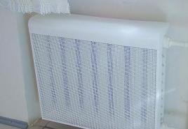
Appearance The assembled VHF radio receiver is shown in fig. 6.

Figure 6. Appearance of the VHF radio receiver
A complete list of kits is available on the Master Kit website.
This circuit is powered by just one 1.5V battery. An ordinary earphone with a total impedance of 64 ohms was used as an audio playback device. Battery power runs through the headphone jack, so just pull the headphones out of the jack to turn off the receiver. The sensitivity of the receiver is sufficient to use several high-quality HF and LW stations on a 2-meter wire antenna.

Coil L1 is made on a ferrite core 100 mm long. The winding consists of 220 turns of PELSHO 0.15-0.2 wire. Winding is carried out in bulk on a paper sleeve 40 mm long. The tap must be made from 50 turns from the grounded end.
Receiver circuit with just one field-effect transistor
This circuit variant of a simple single-transistor FM receiver operates on the principle of a super-regenerator.

The input coil consists of seven turns of 0.2 mm copper wire wound on a 5 mm mandrel with a tap from the 2nd, and the second inductance contains 30 turns of 0.2 mm wire. The antenna is a typical telescopic one, powered by one Krona battery, the current consumption is only 5 mA, so it will last for a long time. Tuning to the radio station is carried out by a variable capacitor. At the output of the circuit, the sound is weak, so almost any home-made ULF is suitable for amplifying the signal.

The main advantage of this scheme in comparison with other types of receivers is the absence of any generators and therefore there is no high-frequency radiation in the receiving antenna.
The radio wave signal is received by the receiver antenna and separated by a resonant circuit on the inductance L1 and capacitance C2 and then fed to the detector diode and amplified.

FM receiver circuit on a transistor and LM386. |
I present to you a selection simple circuits FM receivers on the range 87.5 to 108 MHz. These schemes are quite simple to repeat, even for beginner radio amateurs, they are not large in size and can easily fit in your pocket.


The circuits, despite their simplicity, have high selectivity and a good signal-to-noise ratio, and it is quite enough for comfortable listening to radio stations.
The basis of all these amateur radio receiver circuits are specialized microcircuits such as: TDA7000, TDA7001, 174XA42 and others.

The receiver is designed to receive telegraph and telephone signals from amateur radio stations operating in the 40-meter range. The path is built according to a superheterodyne scheme with one frequency conversion. The receiver circuit is built in such a way that a widely available element base is used, mainly KT3102 type transistors and 1N4148 diodes.
The input signal from the antenna system is fed to the input band-pass filter on two circuits T2-C13-C14 and T3-C17-C15. Connecting the maenad circuits is the capacitor C16. This filter selects a signal within 7 ... 7.1 MHz. If you want to work in a different range, you can rebuild the circuit accordingly by replacing the transformer coils and capacitors.

From the secondary winding of the TK RF transformer, the primary winding of which is the second filter element, the signal is fed to the amplifying stage on the VT4 transistor. The frequency converter is made on diodes VD4-VD7 in a ring circuit. The input signal goes to primary winding transformer T4, and the signal of the smooth range generator to the primary winding of the transformer T6. The smooth range generator (GPA) is made on transistors VT1-VT3. Actually the generator is assembled on the transistor VT1. The generation frequency lies within 2.085-2.185 MHz, this range is set by a loop system consisting of inductance L1, and a branched capacitive component of C8, C7, C6, C5, C3, VD3.
Tuning within the above limits is carried out by a variable resistor R2, which is a tuning organ. It regulates the DC voltage on the VD3 varicap, which is part of the circuit. The tuning voltage is stabilized using a Zener diode VD1 and a diode VD2. In the process of establishing the overlap in the above frequency range is set by adjusting the capacitors SZ and Sb. If you want to work in a different range or with a different intermediate frequency, a corresponding restructuring of the GPA circuit is required. This is not difficult to do with a digital frequency counter.
The circuit is connected between the base and the emitter (common minus) of the transistor VT1. The PIC required to excite the generator is taken from a capacitive transformer between the base and emitter of the transistor, consisting of capacitors C9 and CJU. The RF is emitted at the emitter VT1 and fed to the amplifying-buffer stage on transistors VT2 and VT3.
Load - on the RF transformer T1. From its secondary winding, the GPA signal is fed to the frequency converter. The intermediate frequency path is made on transistors VT5-VT7. The output impedance of the converter is low, so the first cascade of the IF is made on the transistor VT5 according to the scheme with common base. From its collector, the amplified IF voltage is fed to a quartz filter, three-section, at a frequency of 4.915 MHz. In the absence of resonators for a given frequency, you can use others, for example, at 4.43 MHz (from video equipment), but this will require changing the settings of the GPA and the quartz filter itself. The quartz filter is unusual here, it differs in that its bandwidth can be adjusted.
Receiver circuit. The adjustment is carried out by changing the capacities included in the meedu by the filter links and the common minus. For this, varicaps VD8 and VD9 are used. Their capacitances are regulated using a variable resistor R19, which changes the reverse DC voltage on them. The filter output is to the T7 RF transformer, and from it to the second cascade of the IF, also with a common base. The demodulator is made on T9 and diodes VD10 and VD11. The reference frequency signal is supplied to it from the generator to VT8. It should have a quartz resonator the same as in the quartz filter. The low-frequency amplifier is made on transistors VT9-VT11. The scheme is two-stage with a push-pull output stage. Resistor R33 controls the volume.
The load can be both a speaker and headphones. Coils and transformers are wound on ferrite rings. For T1-T7, rings with an outer diameter of 10 mm are used (imported T37 types can be used). T1 - 1-2=16 vit., 3-4=8 vit., T2 - 1-2=3 vit., 3-4=30 vit., T3 - 1-2=30 vit., 3-4= 7 vit., T7 -1-2=15 vit., 3-4=3 vit. T4, Tb, T9 - triple folded wire 10 turns, unsolder the ends according to the numbers on the diagram. T5, T8 - double folded wire 10 turns, solder the ends according to the numbers on the diagram. L1, L2 - on rings with a diameter of 13 mm (imported type T50 can be used), - 44 turns. For all, you can use the PEV wire 0.15-0.25 L3 and L4 - ready-made chokes 39 and 4.7 μH, respectively. Transistors KT3102E can be replaced by other KT3102 or KT315. Transistor KT3107 - on KT361, but it is necessary that VT10 and VT11 be with the same letter indices. Diodes 1N4148 can be replaced with KD503. The installation was carried out in a volumetric way on a piece of foil fiberglass with dimensions of 220x90 mm.
This article describes three simplest receivers with a fixed tuning to one of the local stations in the MW or LW range, these are extremely simplified receivers powered by the Krona battery, located in subscriber speaker cabinets containing a speaker and a transformer.
The circuit diagram of the receiver is shown in Figure 1A. Its input circuit is formed by the coil L1, the capacitor cl and the antenna connected to them. Tuning the circuit to the station is carried out by changing the capacitance C1 or the inductance Ll. The voltage of the RF signal from part of the turns of the coil is fed to the diode VD1, which acts as a detector. From the variable resistor 81, which is the load of the detector and the volume control, the low frequency voltage is supplied to the base VT1 for amplification. The negative bias voltage at the base of this transistor is created by the DC component of the detected signal. Transistor VT2 of the second stage of the bass amplifier has a direct connection with the first stage.

The low-frequency oscillations amplified by it through the output transformer T1 are fed to the loudspeaker B1 and converted into acoustic oscillations. The scheme of the receiver of the second option is shown in the figure. The receiver assembled according to this scheme differs from the first version only in that transistors of different types of conductivity are used in its bass amplifier. Figure 1B shows a diagram of the third version of the receiver. Its distinctive feature is the positive feedback provided by the L2 coil, which significantly increases the sensitivity and selectivity of the receiver.
To power any receiver, a battery with a voltage of -9V is used, for example, "Krona" or composed of two 3336JI batteries or separate elements, it is important that there is enough space in the housing of the subscriber loudspeaker in which the receiver is assembled. While there is no signal at the input, both transistors are almost closed and the current consumed by the receiver in rest mode does not exceed 0.2 mA. The maximum current at the highest volume is 8-12 mA. the antenna is any wire about five meters long, and the grounding is a pin driven into the ground. When choosing a receiver circuit, local conditions must be taken into account.
At a distance of about 100 km to the radio station, when using the above indicated antenna and grounding, loud-speaking reception by receivers is possible according to the first two options, up to 200 km - the scheme of the third option. With a distance to the station of no more than 30 km, you can get by with an antenna in the form of a wire 2 meters long and without grounding. The receivers are mounted by volumetric mounting in the housings of subscriber loudspeakers. The loudspeaker rework comes down to installing a new volume control resistor combined with a power switch and installing antenna and ground sockets, while an isolation transformer is used as T1.
Receiver circuit. The coil of the input circuit is wound on a segment of a ferite rod with a diameter of 6 mm and a length of 80 mm. The coil is wound on a cardboard frame so that it can move along the rod with some friction. To work in the MW range, there should be 120 turns with a tap from the middle of the same wire, the feedback coil for the receiver of the third option is wound on a loop coil, it contains 8-15 turns. Transistors must be selected with a gain Vst of at least 50.
Transistors can be any low-frequency germanium of the appropriate structure. The transistor of the first stage should have the lowest possible reverse collector current. The role of the detector can be performed by any diode of the D18, D20, GD507 and other high-frequency series. The variable resistor of the volume control can be of any type, with a switch, with a resistance of 50 to 200 kilo-ohms. It is also possible to use a regular subscriber loudspeaker resistor, usually resistors with a resistance of 68 to 100 kΩ are used there. In this case, a separate power switch will have to be provided. A tuning ceramic capacitor KPK-2 was used as a loop capacitor.
Receiver circuit. It is possible to use a variable capacitor with a solid or air dielectric. In this case, you can enter a tuning knob into the receiver, and if the capacitor has a sufficiently large overlap (in a two-section one, two sections can be connected in parallel, the maximum capacitance will double in this case), you can receive stations in the LW and MW range with one medium-wave coil. Before tuning, you need to measure the current consumption from the power source with the antenna turned off, and if it is more than one milliamp, replace the first transistor with a transistor with a lower reverse collector current. Then you need to connect the antenna and by rotating the rotor of the loop capacitor and moving the coil along the rod, tune the receiver to one of the powerful stations.
Converter for receiving signals in the range of 50 MHz. The intermediate frequency is chosen equal to 4.43 MHz (quartz from video equipment is used)
Magnetic ferrite antennas are good for their small size and well-defined directivity. The antenna rod must be horizontal and perpendicular to the direction of the radio. In other words, the antenna does not receive signals from the ends of the rod. In addition, they are insensitive to electrical interference, which is especially valuable in large cities, where the level of such interference is high.
The main elements of a magnetic antenna, denoted in the diagrams by the letters MA or WA, are an inductor wound on a frame made of insulating material and a core made of high-frequency ferromagnetic material (ferrite) with high magnetic permeability.
Receiver circuit. non-standard detector |
Its scheme differs from the classical one, first of all, by a detector built on two diodes, and a coupling capacitor, which allows you to select optimal load loop detector, and thus, get the maximum sensitivity. With a further decrease in capacitance C3, the resonance curve of the circuit becomes even sharper, i.e., the selectivity increases, but the sensitivity decreases somewhat. The oscillatory circuit itself consists of a coil and a variable capacitor. The inductance of the coil can also be changed over a wide range by pushing and pulling the ferrite rod.
"Scientific and technical articles"- selection scientific and technical articles electronic themes: novelties electronic components, scientific developments in the field of radio engineering and electronics, articles on stories development of radio engineering and electronics, new technology and construction methods and development electronic devices, promising technology future, aspects and dynamics of development of all areas of radio engineering and electronics, exhibition reviews electronic topics.
In the last decade, VHF receivers have been widely and ubiquitously used. This is due to the constantly growing number of radio stations in various directions, as well as the high sound quality of FM receivers compared to AM and the possibility of stereo sound. However, in the post-Soviet space there are a number of problems with the quality of commercially available radios and their use in large cities, in the presence of a large number radio stations and difficult electromagnetic environment. The author of this article considers the position of the Russian market of VHF radio receivers, their shortcomings and options for solving these problems. All this is characteristic not only of Russia, but will be true in Belarus as well.
A look at the Russian market
Classifying household receivers according to consumer functions, one can see that the domestic market contains:
- battery powered miniature receivers;
- small stationary devices with mains/combined power supply;
- VHF receivers as part of music centers;
- car radios and car receivers.
But you will not find domestic household VHF receivers, with the possible exception of car radios of the Ural family. Why? The answer seems to be obvious - in the field of portable devices, where the main thing is the minimum cost, you can't compete with the products of the countries of the South-Eastern region (mainly China). There is no talk at all about music centers and car radios - the domestic industry has never been able to produce technologically sophisticated equipment for such a low price with high quality. In the same receivers of the Ural family, the mechanical components - both the tape drive mechanism and the CD player - are exclusively of imported origin. Stationary receivers with mains power, as it were, fell out of the circle of interests of manufacturers. What is available on the market today is either the same portable products with mains power, or VHF tuners as part of various devices (for example, alarm clocks) and music centers. The former, as a rule, have inherent functional deficiencies, while the latter have a rather high price. In addition, if desired, you can find a high-quality radio - but it will be multi-band. Does the mass consumer in the city need a long-medium-shortwave receiver today? After all, the quality of the received amplitude-modulated (AM) signal in these ranges is extremely low and cannot compete with the frequency-modulated (FM) VHF signal, especially in the city, due to both the properties of wave propagation and modulation features. And additional reception ranges in an expensive device are additional money paid for virtually nothing.
At the same time, in Russia the need for stationary VHF receivers may be even higher than in many other countries. In fact, even today a rare housewife in the kitchen (secretary in the office, saleswoman in the stall) does without a radio. And if there is not enough money for an expensive device, you have to use either radio broadcast receivers for wired broadcasting ("three-programmers"), or simple Chinese-made VHF receivers, at best - with the Panasonic brand. It is clear that radio broadcasting networks cannot compete with VHF stations - neither in the number of programs, nor in the quality of the transmitted signal. Therefore, VHF receivers - for summer cottages, for kitchens, even for work - will be sold in Russia for a long time to come. Suffice it to recall the size of the park of wire broadcasting receivers ("kitchen radio"), and the potential capacity of this consumer niche becomes clear. And here they may appear national characteristics this market, providing a certain chance for domestic producers.
Features of the Russian air
What distinguishes the requirements for VHF receivers in Russia? Let's define that we are talking about inexpensive devices that use mains power and are designed for long-term listening. The latter means that the requirements for the quality of the reproduced signal are quite high - both in terms of the spectral composition and the presence of interference.
The first significant feature is that in Russia there are two VHF broadcasting bands: 65.8-74.0 and 88-108 MHz, Soviet and Western, respectively. And the differences here are not only in the actual frequency sections of the broadcast - the frequency grid pitch is different, respectively 30 and 100 kHz, as well as the frequency deviation of the FM signal - 50 and 75 kHz. Even the polarization of radio signals emitted by transmitters in the Soviet range is horizontal, and in the western range it is vertical!
In addition, our stereo coding standards are different than in the rest of the world. In stereo broadcasting, the FM signal is modulated with a so-called complex stereo signal (CSS). In the USSR, a system with a polar-modulated (PM) signal was adopted (standard international organization broadcasting and television - OIRT). In this case, the audio signal modulates the subcarrier frequency of 31.25 kHz, but in such a way that the envelope of the positive half-cycles is modulated by the signal of the left stereo channel, and the negative half-cycles are modulated by the signal of the right one. The subcarrier is suppressed by 14 dB. In the standard of the International Advisory Committee on Radio Broadcasting (CCIR), adopted almost all over the world, the 38 kHz subcarrier is completely suppressed during the formation of the CCC, and a 19 kHz pilot tone is transmitted in the receiver to restore it (Fig. 1).
Fig.1. Formation of a complex stereo signal (a) and its representation in the OIRT (6) and CCIR (c) standards.
In addition, in Russia, in the conditions of megacities, there are additional problems associated with the location of transmission centers. For example, for Moscow, Ostankino, Oktyabrskoye Pole, Balashikha, Shabolovka is far from a complete list of transmitter geography. As a result, depending on the receiving point, the signal level on adjacent channels (with a spacing of about 300-400 kHz) can differ by tens of decibels, which imposes special requirements on the dynamic range and selectivity of receivers.
Anatomy of a VHF receiver
The classical scheme of the VHF receiver of the FM signal is shown in fig. 2. This is a single frequency conversion receiver (superheterodyne circuit). The signal from the antenna enters the high-frequency (HF) path, which includes a preselector (input band-pass filter and high-frequency amplifier - UHF), as well as a local oscillator with a mixer. UHF not only amplifies the signal, but also filters it in a given band. The amplified RF signal enters the mixer, which ideally implements the function U=u n cos(2n f n t)· u ub> G cos(2n f G t), where f n , u n And f G u G- frequency and amplitude of the input signal and the local oscillator signal, respectively. After the mixer, the signal (up to amplitude) has the form cos2p( f n +f G)t+cos2p( f n - f G)t, which corresponds to modulated carrier signals f n +f G and | f n -f G|. Difference component - intermediate frequency (IF) f pch =|f n -f G| - allocates with a band-pass filter and further work with it.
The IF signal is filtered and amplified, after which the signal will go to a frequency detector - an FM demodulator (frequency-to-voltage converter). After demodulation, the low-frequency signal is amplified to an audio frequency amplifier and then to playback devices. When broadcasting stereo programs, after the frequency detector, the signal first arrives at the stereo decoder. Of course, we have listed only the most basic functional blocks - without considering such important functions for a home receiver as automatic frequency control, noiseless tuning, comfort noise generation, automatic level control, etc. Tuning to the station frequency occurs by simultaneously changing the frequency of the local oscillator and the LC circuits of the preselector.

Fig.2. Generalized block diagram of a superheterodyne FM receiver.
In superheterodyne circuits, one of the main problems is the need to suppress the signal in the so-called mirror channel. Its nature is clear - since after the mixer, f pch =|f n -f G|, can get into the IF path as a signal with a frequency f n =f G -f pch(if the local oscillator frequency is higher than the tuning signal), and with f h =f G +f pch, i.e. a signal located symmetrically to the tuning frequency relative to the local oscillator frequency. Consequently, f h =f n±2 f pch depending on whether the desired signal is above or below the local oscillator frequency. It is clear that it is necessary to suppress the signal in the mirror channel in the preselector, before the mixer. Moreover, the higher the IF, the greater the separation of the main and mirror channels and the easier it is to solve this problem. But even for a standard 10.7 MHz IF, the mirror channel of the "Soviet" VHF range turns out to be in the 87.2-95.4 MHz region, where some television channels and their soundtrack are located in Russia, and now also radio stations of the western broadcasting range. The paper shows that in this case, the selectivity for the image channel should be at least no worse than 78 dB - and in some cases even as much as 100 dB. Whether it is possible to achieve such a high selectivity in household equipment is a big question.
Not less than important characteristic is the selectivity in the adjacent channel. And for VHF, the allowable separation of adjacent channels when broadcasting various programs from neighboring zones is only 180 kHz. Of course, in almost one zone it is 300-400 kHz. Adjacent channel selectivity is especially important for cities where broadcasting is carried out from several centers, and radio stations adjacent in frequency, but spaced apart in space, can induce signals in the antenna that differ in level by tens of decibels.

Fig.3. Construction of a UKB-receiver on a Philips IC kit.

Fig.4. Structural diagram of the TDA7021 IC.
However, the main problem of the VHF receiver is the need to ensure its low cost, since technically all of the above difficulties are completely solvable. In fact, this is the problem of all household appliances, and it is solved in a standard way - by the release of mass ICs, into which as many functional blocks of the device as possible are integrated. One of the first single-chip tuners was released by Philips back in 1983 - it was the famous TDA7000. The solutions embedded in it turned out to be so successful that it served as a prototype for many ICs - both direct analogues, for example, KS1066XA1, K174XA42, and more advanced circuits from Philips itself. These are ICs such as the TDA7021 with extended bandwidth for stereo reception, and the TDA7088, which includes a search engine and auto tuning to the station frequency. The main advantage of such schemes is the ease of implementation of the device with a minimum of additional components. An example of a completed receiver circuit on the TDA7021 with a stereo decoder (TDA7040T) and an amplifier (TDA7050T) is shown in Fig. 3. Note that for a miniature mono receiver, the last two ICs are not needed.
The downside of this by far the cheapest solution is the low IF, around 70kHz (typically 69-76kHz). Such a low IF made it possible to use active band-pass filters based on operational amplifiers that are part of the receiver IC (Fig. 4). But in this case, the mirror channel turns out to be less than 150 kHz away from the tuning frequency, therefore, there is no selectivity in the adjacent channel. The only thing that saves is that the broadcast channels are actually separated by 300-400 kHz. However, the interference from the image channel increases the noise figure of the receiver by at least 3 dB. It is clear that an increase in sensitivity at such a low selectivity will not lead to anything good. In addition, in the range of 88-108 MHz, the maximum deviation of ±75 kHz practically coincides with the IF, and in the path of such an IF, nonlinear distortions of the FM signal are inevitable. Therefore, a negative frequency feedback (SFN) is introduced into the circuit, which limits the frequency deviation of the received FM signal. Thanks to the SFN, not only the deviation is reduced to 15-20 kHz, but also the local oscillator tuning accuracy is improved - frequency auto-tuning is implemented. The SFN signal is formed by a limiting amplifier after the frequency demodulator, and it controls the tuning varicaps of the local oscillator (see Fig. 4). However, as the bandwidth of the signal decreases, its dynamic range decreases, and therefore the quality of the audio signal deteriorates. The inevitable distortions at the peaks of deviation also lead to a deterioration in perception. Since the same varicap is used in the IC both in the frequency-setting local oscillator circuit and in the frequency feedback loop, the local oscillator tuning slope is different at the beginning and end of the range, and, consequently, the level of the output low-frequency signal is also different. ICs of the TDA70xx family and their analogues are described many times and in detail (for example, in work). It is important for us to state that VHF receivers based on these ICs are unacceptable for Russian megacities, if we are not talking about toys.
Of course, all of these problems are well known, so many specialized ICs for radio equipment with a standard 10.7 MHz IF are produced. One of many examples is the TEA5711 stereo AM/FM receiver (Figure 5). The scheme of its inclusion is shown in Fig.6. This IC contains a stereo channel decoder - but in the CCIR standard. Philips also produces a VHF receiver IC without a stereo decoder - TEA5710. Actually, there are quite a lot of similar circuits (with and without a stereo decoder) today - they are produced by companies such as Sony (CXA1238 and 1538), Sanyo, Matsushita, Rohm, Toshiba, etc. (the element base of modern receivers is considered in more detail, for example, in the work) .
However, with all the diversity of the modern element base, almost all inexpensive models in Russia are represented by fairly similar Chinese-made receivers, at best with an IF of 10.7 MHz, supporting the ranges of 65.8-74 and 88-108 MHz, with tuning to the station by rotating vernier. As a rule, these are single-band receivers designed for a frequency interval of 65-108 MHz. As a result, the received frequencies are at the edges of their operating range. With such a large overlap, it is extremely difficult to ensure the coupling of the input filter and the frequency-setting local oscillator circuit, and tuning is carried out by simultaneously rebuilding the variable capacitors in these LC circuits. They have a different overlap ratio and, as a rule, good pairing can be achieved at three points - at the edges and in the middle of the range, which leads to uneven receiver sensitivity over the range. In addition, such a large overlap with an uneven distribution of broadcast channels (at the edges) makes it extremely difficult to tune into a station - often the program is separated from the program by turning the tuning knob by fractions of a degree. It is clear that it is impossible to determine the frequency value on the tuning scale of such a radio receiver.

Fig.5. Block diagram of the TEA5711 stereo tuner IC.
In addition, the need for high noise immunity of the city receiver imposes increased requirements on the tuning accuracy of all circuits - and there are several of them, and they contain high-quality inductors made as a separate element. Setting up these nodes does not fit well with the ideology of mass production through low-skilled personnel. As a result, almost all Chinese-made VHF receivers differ not only in rather primitive circuitry and ill-conceived design in terms of noise immunity. For the most part, their internal nodes are simply not configured - after all, the receiver somehow works somewhere, and how well the manufacturer is not interested.
What kind of receiver does Russia need?
A few years ago, employees of the Postamarket company asked this question, announcing, with the participation of the Ekho Moskvy radio station, a competition for the best VHF receiver solution for Russia. As mandatory requirements, work in two VHF bands was indicated, the possibility of digital tuning with memorization of at least 10 stations, indication of the tuning frequency, the presence of a socket for connecting an external television antenna, external mains power, confident operation in a complex electromagnetic environment of a metropolis, high manufacturability and low cost. Unfortunately, the organizers were presented with only one interesting solution from the development team of the Research Institute of RP - but it really met their difficult requirements. What is its essence? The developers decided to abandon the classical scheme of a superheterodyne receiver with a single frequency conversion and proposed the generally known principle of infrared reception, when the IF is significantly higher than the operating frequency range. This method was sometimes used in expensive stationary AM receivers, but in the VHF band this approach seemed prohibitively expensive. However, the elemental base is developing, and what was exclusive yesterday, today turns out to be massive and inexpensive.

Fig.6. Wiring diagram for TEA5711 with ULF TDA7050T.
With the infradyne scheme, the preselector is made non-tunable and broadband - for the entire reception range, which greatly simplifies its design. True, the inevitable price for this is that the input circuits (filters, UHF, mixer) must have a wide dynamic range and high linearity. But this is already a circuitry problem, which can be completely solved with a modern element base. Tuning to the station is carried out exclusively by tuning the frequency of the first local oscillator.
The scheme proposed by the developers (see Fig. 7) uses two separate input band-pass filters for the ranges of 65.8-74 and 88-108 MHz and double frequency conversion. The first IF is 250 MHz, therefore, the frequency of the first local oscillator should be in the range of 315-360 MHz. Thus, the mirror channel turns out to be very far from the working one - above 565 MHz, and there are no problems with its suppression by the input filter.
Perhaps the key element of this receiver is the IF filter. Its frequency response should be almost rectangular, with a bandwidth of 250 kHz at a center frequency of 250 MHz. Having managed to solve this problem, the developers received a receiver with only one tunable element (the first local oscillator). After the IF filter, the signal is converted to the second IF - already standard, 10.7 MHz. In this case, the second local oscillator is tuned to a fixed frequency, and all further signal processing is implemented by standard elements of a well-developed and cheap 10.7 MHz IF path. In other words, the local oscillator frequency is fixed in a standard superheterodyne receiver, and instead of a tunable complex preselector, a broadband non-tunable preselector and a highly linear high-frequency path up to the first IF are introduced. This made it possible to solve the problems of selectivity in the mirror and adjacent channels and to prevent non-linear combination noise.

Fig.7. Functional diagram of an infrared ultrasonic receiver with a broadband preselector.
Note that until relatively recently, a significant problem was the lack of a stereo decoder IC that supports both the CCIR (pilot tone) and OIRT (PM) standards. However, it has disappeared since Angstrem began to produce IS KR174XA51 - a stereo decoder with PLL synchronization, with automatic and forced determination of decoding standards (Fig. 8).
However, Angstrem produces an IC kit for a VHF receiver. But since this enterprise is focused on the market of the South-Eastern region, the KR174XA34 tuner IC produced by it is designed for low IF, about 70 kHz. Above, we talked about the lack of such tuners and their unsuitability for high-quality receivers, especially in Russia. However, the market for tuner ICs is quite large and there are plenty to choose from. For example, the Minsk NPO Integral produces ILA1238NS and ILA1191NS microcircuits - analogues of the well-known Sony CXA1238 and СХА 1191 ICs (stereo and mono receivers designed for 10.7 MHz IF).
An extremely important aspect is receiver control. There are more than thirty radio stations in both VHF bands in Moscow, and not much less in other large cities. Therefore, digital tuning with a memorization of at least 10 stations and an indication of the receiving frequency is not a luxury, but a necessary requirement for a stationary receiver. But with today's variety of frequency synthesizers, indicators of all types and their controllers, as well as universal microcontrollers, there are no problems with an inexpensive implementation of this function - up to control via infrared. There is no digital tuning in cheap Chinese models, and this is another potential "plus" for domestic manufacturers. However, there are cheap Chinese VHF receivers with digital tuning. (As a rule, the tuning system works in them too, but not in the receiver itself.)
Thus, there are prerequisites for the production of a unique domestic receiver - a "kitchen VHF radio". First of all, inexpensive foreign models cannot cope with the difficult interference environment and broadcasting features in large Russian cities. In addition, they have a primitive, and therefore too inconvenient user interface. Finally, only expensive models fully support operation in two Russian VHF bands, especially in terms of stereo reception (but the inherent disadvantages of devices with a standard 10.7 MHz IF remain with them). At the same time, the implementation of all additional functions is a fairly simple task compared to high-quality signal reception and does not significantly increase the cost of the product, especially in mass production. But the scheme of the tuner itself deserves the closest attention, and the concept of an infra-line VHF receiver proposed and tested by the developers of the Research Institute of RP can become the very missing link that can combine high quality and low price - unless, of course, someone offers more optimal solution.
What is not in Russia
The only thing that is not available in our country for mass VHF receivers is the possibility of manufacturing modern cases. After all, a radio receiver, like any household appliance, is not only a carrier of a technical function, but also an interior element, an object that should please the eye. And without a variety of high-quality cases, the most interesting and promising development will remain inside the breadboard box. Without solving the problem of producing high-quality plastic products, so seemingly far from electronics, the production of electronic household appliances in Russia is impossible. And this is a matter of investing money in the purchase of equipment and, most importantly, in mold development technology. One manufacturer, probably, can not afford it. Of course, cases (or molds) can be ordered in the same China - but, firstly, this is quite an expensive pleasure, and secondly, in this case it is extremely difficult to guarantee that these cases will be not only with their customer, but and from everyone who wants to buy them. They treat copyrights and pirated copies in a very peculiar way - according to Western concepts. And protection from this is again a lot of money.
But maybe radio stations are interested in their programs reaching as many potential listeners as possible. And that the reception quality of their signal was high enough? So isn't it time in Russia to organize a consortium of developers, manufacturers of VHF equipment and broadcasting enterprises? Similar consortiums for the development of advanced technologies are common throughout the world. Although VHF broadcasting is not a new technology, but since in Russia there is a problem that is beyond the strength of one manufacturer, but many are potentially interested in solving, maybe the path of cooperation will bring results?
Sources
- Kononovich L.M. Modern broadcasting receiver - M .: Radio and communication, 1986.
- Polyakov V. Single-chip FM receivers. - Radio, 1997, No. 2.
- Kulikov G., Paramonov A. Radio receiving paths of household audio equipment (parts 1 and 2). - Repair of electronic equipment, 2000, No. 2-3.
The article describes the simplest VHF converter for receiving radio stations of the "European" range of 88-108 MHz on domestic radios. The design has been repeated over 200 times over several years.
Scheme VHF Converter
In the converter circuit, the absence of scarce parts, ease of execution, configuration without devices, and stability of the circuit are the main features of the described device. A few years ago, an urgent need arose - to ensure the reception of radio stations in the European part of the VHF band (88-108 MHz). Initially, these stations began to appear in the countries of the former socialist camp, like mushrooms after rain, and then in our country.
At first, a big obstacle to progress was the lack of this range in the Soviet standard, and hence the mass radio receivers for its reception. A VHF converter came to the rescue. At one time, circuits of varying degrees of complexity were tested - from three transistors to one transistor.
At the same time, it turned out that in most cases the simplest one-transistor option was optimal. It should be noted right away that the diode mixer in most cases was significantly inferior to the transistor frequency converter in terms of frequency transfer (transformation) and harmonic spectrum.
According to the diagram in Fig. more than two hundred (200!) converters were made on the site. Not a single discrete element of the circuit was selected, and the deviations of the nominal values reached 20%. Transistors were installed without checking the gain. The frequency converter is made on a transistor VT1 type KT315 with any letter index. All contours without cores. Input circuit P and output L4 are wound with PEV-1-0.8 wire. The communication windings L2, L5 and the heterodyne circuit 13 are wound with PEV-1-0.18 wire. Number of coil turns: L1 - 6 turns; L2, L5 - 2 turns; L3 - 3 + 13 vit.; L4 - 7 vit.
First, on a 04 mm mandrel (using a drill shank), a coil L1 is wound round to round. The conclusions are cleaned of enamel, and the coil is soldered into the board. Then the coupling coil L2 is wound. The drill is not yet removed from the coil. The end of the wire is cleaned of enamel and soldered into the board. The connection winding is wound between the turns of the loop coil. Then the second end of the communication coil is soldered into the board, and the drill-mandrel is removed from the coil. The extreme turns of the contour coil are slightly moved apart. Coils L4 and L5 are wound and soldered in the same way.
The local oscillator coil L3 is wound on a plastic rod with a diameter of about 3.5 mm (vinyl rods from snow blower brushes were used). After stripping the insulation of the leads, the coil is soldered into the board. Then the rest of the parts are mounted. The length of their pins is minimal, so the height of the board is very small.
All capacitors of the circuit may have deviations from the values \u200b\u200bspecified on the diagram up to 20%, the resistor - more than 30%. KT315 transistors were used with different letter indices, i.e. with a spread of gains over a very wide range.
The capacitance of capacitor C6, in general, ranged from several thousand pF to 0.1 microfarad. It did not affect the operation of the converter.
The conclusions of all elements had a minimum length. The whole setting consisted in choosing the working section of the range, namely the section. For some reason, most authors of articles bypass this issue. And then their followers wonder why it is not possible to receive radio stations of the entire VHF range on the converter? The range covered by the original radio is about 1 MHz (65.9-74 MHz).
Without changing the frequency overlap of this radio receiver, but only by transferring its setting to another section of the VHF band with a converter, of course, it is possible to ensure reception of only the same frequency band (about 10 MHz). And no more. And the new VHF range, according to the standard, occupies the 20 MHz band (88-108 MHz), i.e. twice as big. This means that without expanding the reception bandwidth of a standard VHF receiver, especially with a fixed converter local oscillator setting, it is impossible to receive stations of the entire “European” VHF band.
This comes at a price for the simplicity of the converter circuitry. It remains only to choose the correct frequency for tuning the local oscillator of the converter, so as not to lose at least what is left.
Before adjusting the converter, the turns of the coils L2 and L4 are slightly pushed apart. The output of the converter is connected to the antenna socket of the VHF radio receiver. The value of the supply voltage of the converter is not critical. The operability of the circuit was tested when powered by a 5-12 V source, therefore, as a rule, the supply voltage of the main radio receiver circuit is used.
By tuning the main radio receiver, they achieve the reception of any radio station of the new VHF band. Slightly pushing the turns of the heterodyne circuit L3 of the converter, the received part of the subband is shifted. Sometimes, with large deviations in the capacitance of the capacitor C4, it may be necessary to reduce the number of turns L3 by 1-2 turns. Having achieved reception of the required radio station, check the setting of L1 and L4. If, when a metal needle (drill) is introduced into these circuits (alternately), the signal of the received station increases, then the turns of these coils must be slightly moved apart.
An increase in the volume of the received radio station with the introduction of a thin ferrite core indicates the need to compress the turns of the coil. And the last. It is hardly necessary to select the capacitor of the local oscillator circuit of the converter C4 according to the value of TKE. Indeed, almost all radio receivers to which converters will be connected have and use APCG. Accordingly, fluctuations in the supply voltage of the converter had practically no effect on the stability of the reception, and no significant effect of the shielding of the converter was noticed when it was built into the radio receiver, so shielding was not performed.
 Naturally, after minor changes in the circuit, the converter can be used with radios that have a grounded plus of the power source. To do this, you can go two ways. Change the type of conductivity used in the converter transistor or change the connection points of the common terminals of the coils L2.15. They can now be combined with a common power plus. The mass of the converter is isolated from the body of the radio receiver.
Well, the simplest solution is to connect the antenna to the converter and the converter itself to the radio receiver through two small capacitors.
The PCB drawing is shown in Fig.2. In conclusion, I would like to note that the stability of the converter's operation was primarily affected by the stability of the parameters of all circuits. Especially under vibration conditions (on motor vehicles), therefore, the circuits were wound with a rather thick wire, and after setting the circuit, they were filled with molten (soldering iron) paraffin. The printed circuit board was covered with several layers of varnish after desoldering all the elements and tuning.
Simplest VHF FM receiver, available for repetition by a novice radio amateur, can be assembled according to the scheme of a single-transistor synchronous-phase detector. A schematic diagram of such a receiver is shown in the figure.
The signal is received by the WA 1 antenna, the role of which can be played by a piece of mounting wire. This signal enters the oscillatory circuit L1C2, by adjusting the capacitor C2, the circuit can be tuned within the VHF FM range of 65.8-73 MHz. The signal voltage allocated by this circuit is fed through the capacitor C3 to the base of the transistor VT1. This transistor stage performs several functions simultaneously: the functions of a phase detector, a low-pass filter, a DC amplifier, and a low-frequency amplifier. Phase detection occurs on p-n transitions transistor equivalent to diode junctions. You can assemble the receiver by volumetric wiring, or you can design a printed circuit board based on circuit diagram, and arrange the details on it in the same order as in the diagram. Coil L1 does not have a frame, for winding a drill shank with a diameter of 7 mm is taken and a coil is wound on it with a PEV wire of 0.4 ... 0.5 mm. Coil L1 contains 14 turns. After winding, the drill is removed from the coil (it only serves as a winding mandrel).
Transistor P416B can be replaced with GT308A, KT603B. Phone - any high-resistance small-sized. Capacitor C2 of the PDA type is ceramic, for 8 ... 30p, 5 ... 20p or 4 ... 15p, it is adjusted by turning the screw located in the middle. As a power source, you can use a Krona 9 V battery. Any switch, for example, a toggle switch.
Setting relatively simple. You need to connect the phone, power and antenna - a piece of mounting wire, the longer the better. It is desirable to hang the antenna out the window or hang it on the window frame. Now you need to put on the headphones (they should have a slight hiss) and by rotating the rotor of the capacitor C2 try to catch one station. If this does not work, you need to stretch the turns of the coil a little and repeat.
Good results cannot be achieved from such a simple receiver, but it can receive two or three stations in the VHF FM band. Experiment with stretching and compressing the turns of the L1 coil, the length and location of the antenna, and the supply voltage. Instead of headphones, you can connect a 1 ... 3 kOhm resistor and, from the connection point of this resistor and the emitter of the transistor, apply low-frequency voltage to the ULF, then you can listen to the speakers.
List of radio elements
| Designation | Type | Denomination | Quantity | Note | Shop | My notepad |
|---|---|---|---|---|---|---|
| VT1 | bipolar transistor | P416B | 1 | To notepad | ||
| C1 | Capacitor | 12 pF | 1 | To notepad | ||
| C2 | variable capacitor | 8-30pF | 1 | To notepad | ||
| C3 | Capacitor | 36 pF | 1 | To notepad | ||
| R1 | Resistor | 330 kOhm | 1 | 0.5W | To notepad | |
| WA1 | Antenna | 1 | To notepad | |||
| IN 1 | Headset | 1 |